
 |
| Check out the NEW Hotbot | Tell me when this page is updated |
|
| Check out the NEW Hotbot | Tell me when this page is updated |
The Hendershot Generator
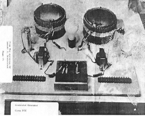
A man by the name of Lester Hendershot claimed to have produced useable electric power from this device in the rangeof 200 to 300 watts in circu 1930
For a time his Son Mark M. Hendershot was working on tryingto duplicate his father but I think he has ceased this and hasbeen unsuccessful to my knowledge and unable to produce resultshis father obtained..
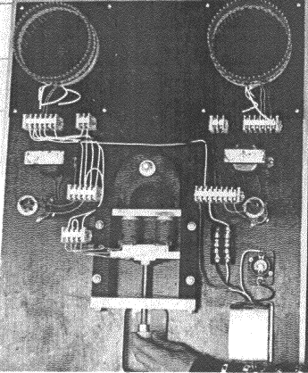
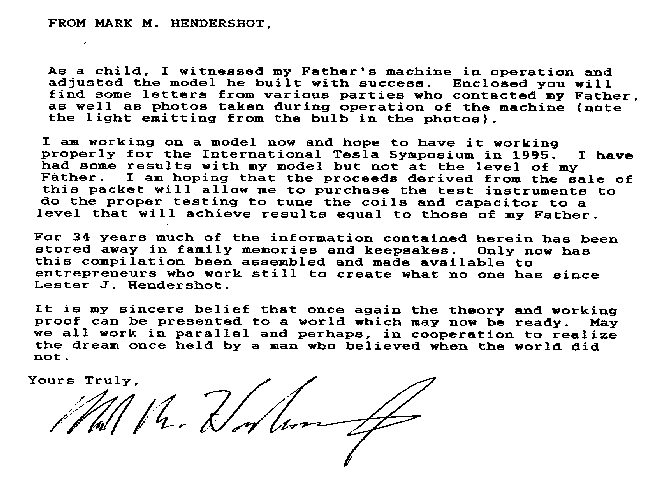
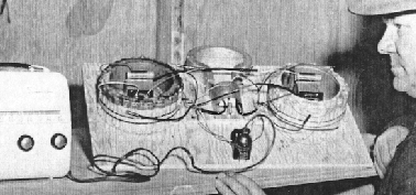
A couple of constuctors did report successful reproduction of this invention although I am unable to confirm it.
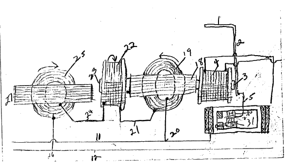
I have heard from others that have been unsuccessful and the information is reproduced for your enlightenment and possible experimentation,if so let me know how you get on. so that others may share inyour discoveries as well.
The following article is taken from the articles from the Archivesof Lester J Hendershot and is reproduced in the spirit that Mark Hendershot has indicated in his letter above.
Tesla Bookshop I believe.
My invention relates to the production of electric current andhas for its object to generate current for power & lighting purposes., and any other uses that it is desired to make of it.
I'm not sure But I believe this relates to an earlier inventionand also the diagrams are missing,.
the second one shown later in this web page is more importantcheck it out for yourself.
Referring to the drawings, in which like parts are similarly designated
Fig 1 is the diagrammatic view of one construction.
Fig.2 is similar view of another construction.
Referring to Fig. 1: I use a shall collector 1, preferably a smallmetallic plate horizontally disposed and having a downwardly extendingflexible strip 2 of magnetic material terminating opposite a core3 of a first coil to be attached thereby.
The strip 2 has soldered to it one end of a copper wire 5, whichmay or may not extend to the collector proper 8, whose other endend is soldered to the middle of the inner winding, or layer ofsecond coil 6.
This coil is composed of turns of no. insulated copper wire, Isprovided with a permanently magnetic core 7, and Is preferablyparallel to the first coil.
The core 7 and its windings 6 lie In the center of a honeycombcoil 3 that has two windings, each composed of turns of no. wire,the windings being cross wound.
The ends of the winding 6 are each connected by connecting wires9 & 10 respectively, to an end of one of the crossed windingsof the honey-comb coil 8 ind the other ends of the windings arethen connected to the power lines or terminals 11 & 12 respectively,
The ends of the first coil 4 are respectively connected to twocoils 13 and 14 wound in opposite directions, each consistingof turns of no. andprovided with soft iron cores 15 and 16 respectively.The coils 4, 13, and 14 are; connected in series in a preferablypermanently closed circuit with a resistance 17 included betweenthe coils 13 & 14, and in the structure that I have made,thisresistance is small of about Meg. Ohms.
The coils l3,l4 are substantially parallel to the honey-comb coil,one an each side of the longatudinal vertical central plane ofthe apparatus. The core 3 is soldered to a set of small transformerplates 18 and forms an extension of these plates.
These plates have openings In their center for the reception ofa fine wire coil 19, composed of turns of no. wire. There is nocore through coil 19. The inner end of coil 19 is connected toone line terminal 11 at 20, and, the outer end is connected bywire 21 to the third coil 22 of turns of no. wire, whose core23 has metallic connection with transformer plates 18. The core23 may be omitted.
The end of the outer turn of coil 22 is connected by wire 24 tothe inner turn of a second fine wire coil 25 like coil 19 butwound in the opposite direction, and the opposite direction ,andthe of this coil is connected at 26 to the other power line terminal12.
The fine wire coil 25 is placed In the interior of laminated transformerplates 27, identical with the plates 18 and the coil has preferablyno metallic core, and the transformer plates 27 are separate fromthose 18. The direction of the winding of the coils is indicatedby arrows,
A lamp or small motor connected across the ends of the power linesor terminals 11 & 12 will operate continuously when the longitudinalaxis of device is directed north and south, and will cease toproduce power when deviated from the north & south direction.
That is to say, the motor will stop or the lamp will cease toglow. To overcome this objection for some purposes, and In orderto permit the structure to operate In any direction which itsaxis is placed, I have modified the structure of coil 8 and theparts within it; all other parts-remaining same.
The extension '2 of plate 1 is connected by wire 5 to a smallpivoted soft iron plate 28 within a short coil 29 of turns ofno. wire, between brass end plates 30 and is held in a soft ironyoke 31 by a screw 32 that passes through one pole end of a ringmagnet 33.
The screw 32 serves to hold the yoke 31 to the magnet po1e endand at the same time holds the toll 29 in the yoke 31. The plate28 is pivoted In one of the brass end plates 30. The coil 8a isa single wire cross wound coil having, 1 turns of No. wire. Oneend of this coil is connected by wire 9 to one end of the coil29, and the other end to the line wire 11. Surrounding this coil8a is a second coil 8b of the same size wire and the same No.of turns. The other end of coil 29 is connected by wire 10 toone end of the second and outer honey-comb coil 8b whose otherend is connected to the other power line terminal 12.
It will be noted in both constructions shown the coil 4 extendsacross one side of the coil 3 or the two coils 8a and 8b and alsoacross the coil 6 or 29.
That coils 6 or 29. lie within the coils 8 or the 8a & 8b, and the axis of coils 4 & 29
.That coils 6 and 29 must be substantially parallel.
Also the axis of coils 13 and 14 are substantially parallelto the honey-comb coils 8, 8a and 8b.
I claim. In an electrical apparatus, a collector, a coil havinga core one end of which is in attracting relationto a portion of said collector, a honey-comb coil having: twowindings connected to power terminals, a second coil in the honeycombcoil each end of which is connected to one of the windings ofthe Honeycomb ,means to send electricity from the collector tosaid second coil , a pair of oppositely wound coils parallel tothe honey-comb coil & constucted in series withthe first coil, a fine wire coil, transformer iron, surroundingfine wire coil, a third coil, a second fine wire coil, tranformeriron surrounding the same, said third coil and fine wire coilsconnected in series across the line.
2.In an electrical apparatus, a collector having an extension,a coil having a core one end of which is in attracting relationto said extension, a honeyonb coil having two windings perpendicularto the coil and its one end connected to lower terminals, a secondcoil within the honey-comb coil, each of which is connected tothe opposite end of one of the honey-comb windings, a permanentmagnet is or in inductive relation to said second coil, meansto send current from the collector to the second coil, a pairof oppositely wound coils, said first coil connected in seriesbetween said pair of oppositely wound coils, a fine wire coil,transformer iron surrounding said coil leaving a continuationthat forms the core of the first coil, a third coil between whichand the first coil said transformer iron, and fine wire coil isarranged a second fine wire coil wound in an opposite directionto the first fine wire coil, transformer iron surrounding thesecond fine wire coil, soli d fine wire coils being connected inseries through the third coil across the power terminals, andthe fine wire coils arranged in rectangular relation to the first& third coils.
3. In an electrical apparatus, a collector, a coil having a coreone end of which is in. attracting relation to a portion of saidcollector, a honey-comb coil having- two windings connected topower terminals, a second coil in the honeycomb coil each endof which is connected to one of the windings of the honeycombcoil, means to send electricity from the collector to the secondcoil, a pair of oppositely wound coils parallel to the honey-combcoil and connected in series with the first coil, a resistancebetween said oppositely wound coils, a fine wire coil, transformerIron surrounding the fine wire coil, a third coil, a second finewire coil, transformer iron surrounding the same, said third coiland fine wire coils connected in series across the line.
4. In an electrical apparatus, a collector, a coil having a coreone end of which, is an attracting relation to a portion of saidcollector, a honey-comb coil having two windings each,connectedat one end to power terminals, a second coil in the honeycombtraverse thereto and parallel to the first coil and connectedto the other ends of the honey-comb windings, a permanent magnetin inductive relation to said second coil means to send currentfrom the collector to said second coil, a pair of oppositely woundcoils parallel to the honeycomb coil, a resistance betweenthe oppositely wound coils, said coils and resistance includedin series in a closed circuit between the ends of the first coil,a fine wire coil, laminated transformer iron surrounding-saidfine wire coil but not passing there through and having an extensionthat forms the core of the first coil,a third coil between whichand the first coil said transformer iron and fine wire coil Isarranged, the first & third coils is being wound in the samedirection, a second fine wire coil doulid in opposize directionto the first fine wire coil, laminated transformer iron surroundingthe second fine wire coil but not passing there through saidcoil connected between the too fine wire coils In series acrossthe power terminals.
5 In an electrical apparatus, a collector ,a coil having a coreone end of which is in a attracting relation to a portion of saidcollector, a honeycomb coil having two windings each connectedto a power terminal, a ring magnet in the honey comb coil ,a secondcoil in the magnet and connected in series between the windingsof the honey comb coil,a pivoted oscillation member within thesecond coil, means to conductively connect said collector andmember,a pair of oppositely wound coils adjacent the honey-combcoil and connected in series with said first coil,a fine wirecoil,transformer iron surrounding the fine wire coil,a third coil,asecond fine wire coil,transformer iron surrounding the last coil,saidthird coil and fine wire coils connected in series across thepower terminals.
6 In an electrical apparatus , a collector, a coil having a corein attracting relation to said collector, a honey-comb coil handingtwo windings each connected to a power terminal, a ring magnetin the honey-comb coil, a second coil in the magnet whose axisis at right angles to the axis of the honeycomb coil, a pivotedoscillating member within the second coil, means to conductivelyconnect the collector and member, a pair of oppositely, woundcoils adjacent the honeycomb coils parallel thereto and connectedin series with the first coil, a fine wire coil, transformer ironsurrounding the fine wire coil, a third coil, a second fine wirecoil, transformer iron surrounding the last coil, said third coilconnected In series between the fine wire coils across the powerterminals.
7.In an electrical apparatus, a,collector substantially horizontallydisposed and having a substantially vertical extension, a coilhaving a core in attracting relation to said extension, a honey-combcoil having tuo cross wound windings each of which is connectedat one end to power terminals, a ring magnet within the honey-combcoil, a yoke shaped extension connected to one of the ends ofsaid magnet, a second coil held in said extension parallel tothe first coil, a soft iron member pivoted in the second coil,means to electrically connect said extension and member whilepermitting independent movements thereof, a fine wire coil.laminated transformer iron surrounding the fine wire coiland having an extension that form the core of the first coil,the third coil arranged at right angles to the first coil, a secondfine wire coil wound in a direction opposite to the winding ofthe first fine wire coil and papallel thereto, laminated transformersurrounding the last coil, said third coil arranged between thefine wire coils In series and the series connected across theline terminals.
Two additional capacitors are required for the hand wound capacitorused in center of the basket weave coils and are also, made fromPyramids TM 58 or a suitable substitute type trimmed to size.Coils are identical in construction so only one will be described.
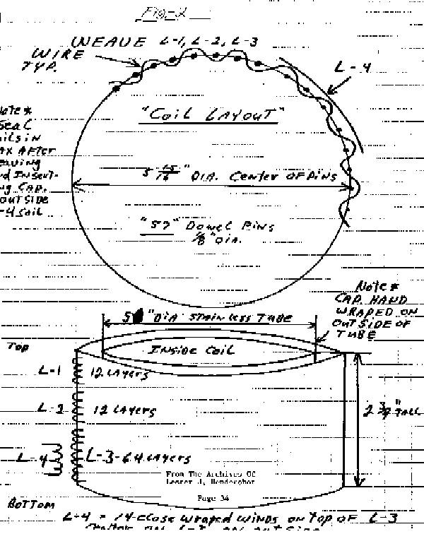
The coil is cylindrical, 5-15/16 diameter (See Fig 2). It is
wound like a basket around fifty seven '1/8 in. diameter wooddowel pins three inches long. The dowel pins are evenly spacedon the circumference of the circle. All coils are wound in thesame direction, weaving in and out between dowel pins mountedin the same type base to hold them rigid. Starting at the base,L3 is 64 turns on No. 24 gauge copper enamel or Formvar wound.Ll and L2 is Belden thermoplastic hookup wire No. 2O gauqe, afoot spool is required for each coil L! and L'-. The 25 feet willend up with 12 turns each wound in the same fashion. Hendershatalways used Ll red and L2 yellow for easy identification.
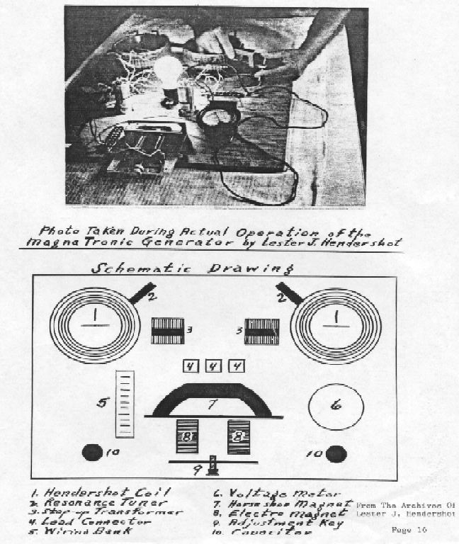
L4 is made from No.18 gauge copper enamel coated or Formvar magnetwire. 14 turns close wound over the outside diameter of L3 inthe center of L3 Plastic electrical tape is wrapped around L3to form a smooth surface for winding, after winding the 14 turns.wrap additional tape to hold L4 in place.
The handwrapped capacitors are the most difficult to build andare the critical key item to success or failure in producing results.The foil from two capacitors, Pyramid electrolytic TM 58, mustbe removed from the can that encloses the foil by cutting thetop or bottom off with a hack saw or other cutting device.Thecoiled foil is removed from two capacitors and spread out on aflat table. A TM 58 capacitor should measure, including foil andpaper, 91-1/8 in. long and 2-3/4 in wide. Wipe off excess electrolyticsolution so that it is dry. One side of the paper holding thefoil will be full length, the opposite side will be split withterminal connections appearing at each end of the split portion.The capacitors that were used in the early experiments had a gapbetween the split foil of 3/4 of an inch. You may use a substitutecapacitor and trim foil to size.
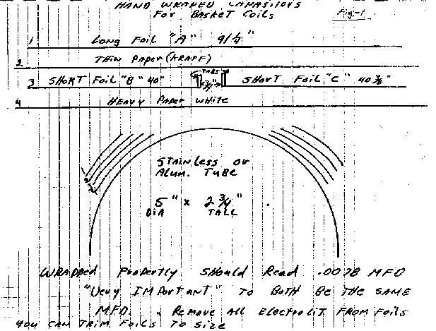
Prepare two cylinders of metal with dimensions of 5 in. in diameterby '7-3/4 in. wide. A stainless steel sheet metal .032 thick wasused in Hendershot's cylinders, open at both ends. Before wrappingbegins, insulate the cylinders with pure craft paper (see Fig.1 & 3). Ordinary brown wrapping paper is unsatisfactory asit contains impurities. Wax paper might be used as a substitute.
It is interesting to note that Hendershot originally used onepound coffee cans for the capacitor cylinders but found that aftera period of time the electrolyte left in the capacitor paper wouldleave perforations in the metal, rendering the cylinder useless.This is why he made the later cylinders of stainless steel.
after insulating the cyclinders wrap the capacitor foil and paperaround each other of the cyclinder.
As shown on the drawings included .
Secure the wrapped capacitor with a string or tape so that itwill not unravel.
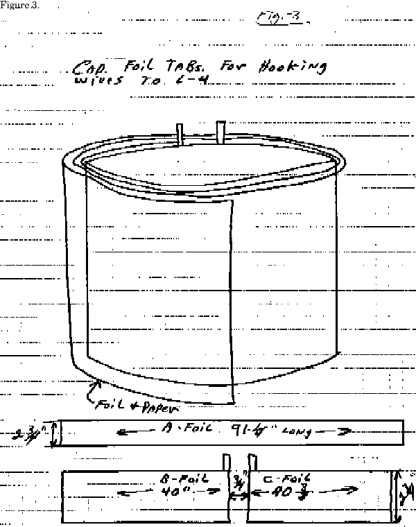
Both units should look th e same
Each of the completed handwound capacitors cyclinders are placedinside the basket weave coils.
After centering pour melted paraffin into the outsider diameterof the cyclinder and inside diameter of the coils.
The melted paraffin will run into the turns of the wire sealingthe complete units.
If correct tension were applied while wrapping the capacitor paperand foil , the measured capacity should be .0078 MFD.
Note: At one time Hendershot's papers said 1.3 MFD.
It is very difficult to obtain the correct capacity and this processmay, have to be repeated many times to arrive at the right valuefor each unit. Short circuits of the capacitor will render theresults useless and of course make it impossible to measure theresultant capacitance value. For accuracy the capacitors shouldbe measured with a reliable capacitor bridge. Hendershot was ableto accomplish this feat intuitively.
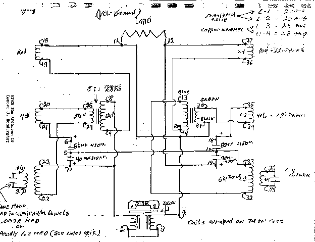
(See figure 4) If all conditions for the circuit are met withthe
proper component values and if the wiring is made according tothe schematic diagram, the unit- should function and produce 300to 500 watts of energy.
The only limiting factor to the amount of power that can be extractedis the
wire size used in the coils and transformers. Hendershot on manyoccasions when applying excessive out-out loads, would burn upthe unit by the over heating of the wirinq. Some variations canbe made in the circuit wirinct but what changes can be made remainunknown at this time.
After a unit was wired either by Hendershot or other experimentershe would sit down at the device with a length of insulated wirebared at each end and begin making connections to various terminalsof the unit until the solenoid-maanet combination would buzz andthe output load, if it was a standard 110 volt Light bulb, wouldglow. He then would adjust the air gap between the magnetand solenoid coils until full brilliance was achieved and thebuzzer produced a steady tone. This procedure would take froma tew minutes to several hours.
On one occasion he adjusted the unit for 10 to 15 minutes andonly achieved a flash of light from the output. Several hourslater he found it necessary to rebuild the capacitors before anyfurther tests could be made. Either the unit would work immediatelyor not at all, depending on the unknown characteristics ofthe phenomena.
2 Dual 40-80 MFD Electrolytic Capacitors 400 Volt Non-Polarized
2 5:1 Ratio 24 Volt to 120 Volt Transformers (Vertical OscillatorType)
Red, Black, Blue, Green Coded Wires
250' #20 AWG Insulated Solid Copper Wire
100' #28 Enamel Copper Wire
500' #24 Enamel Copper Wire
114 311 x 11811 Wood Dowels
1 Horseshoe or U Shaped Magnet
2 Plates for Dowel Pin Mounting
1 Screw Type Adjusting Mechanism
1 1-1/211 x 1180 x 611 Flat Iron Bar (Approx.)
2 Iron Solenoid Cores
Miscellaneous parts, screws, bolts, wire, etc.
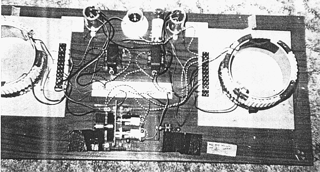
An Australian Constructors setup
 er>
er>The circuit diagram for the Hendershot Generator.




| Search for |

Encyclopedia of free energy now on CD click for more information