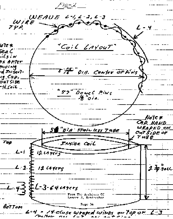
The "Power Capture Unit" consists of a basket weave coil around a specialy wrapped Capacitor positioned in the center of the basket weave coils. The specialy wrapped capacitors were made from Pyramids TM 58 or a suitable substitute type trimmed to size. Coils are identical in construction so only one will be described.
The coil is cylindrical, 5-15/16 diameter (See Fig 2). It is wound like a basket around fifty seven '1/8 in. diameter wood dowel pins three inches long. The dowel pins are evenly spaced on the circumference of the circle. All coils are wound in the same direction, weaving in and out between dowel pins mounted in the same type base to hold them rigid. Starting at the base, L3 is 64 turns on No. 24 gauge copper enamel or Formvar wound. Ll and L2 is Belden thermo-plastic hookup wire No. 2O gauge, a foot spool is required for each coil L! and L'-. The 25 feet will end up with 12 turns each wound in the same fashion. Hendershot always used Ll red and L2 yellow for easy identification.
L4 is made from No. 18 gauge copper enamel coated or Formvar magnet wire. 14 turns close wound over the outside diameter of L3 in the center of L3 plastic electrical tape is wrapped around L3 to form a smooth surface for winding, after winding the 14 turns. Wrap additional tape to hold L4 in place.
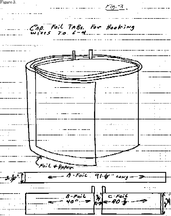
The hand wrapped capacitors are the most difficult to build and are the critical key item to success or failure in producing results. The foil from two capacitors, Pyramid electrolytic TM 58, must be removed from the can that encloses the foil by cutting the top or bottom off with a hack saw or other cutting device. The coiled foil is removed from two capacitors and spread out on a flat table. A TM 58 capacitor should measure, including foil and paper, 91-1/8 in. long and 2-3/4in wide. Wipe off excess electrolytic solution so that it is dry. One side of the paper holding the foil will be full length, the opposite side will be split with terminal connections appearing at each end of the split portion. The capacitors that were used in the early experiments had a gap between the split foil of 3/4 of an inch. You may use a substitute capacitor and trim foil to size.
Prepare two cylinders of metal with dimensions of 5 in. in diameter by 2 & 3/4 in. wide. A stainless steel sheet metal .032 thick was used in Hendershot's cylinders, open at both ends. Before wrapping begins, insulate the cylinders with pure craft paper (see Fig.1 & 3). Ordinary brown wrapping paper is unsatisfactory as it contains impurities. Wax paper might be used as a substitute.
It is interesting to note that Hendershot originally used one pound coffee cans for the capacitor cylinders but found that after a period of time the electrolyte left in the capacitor paper would leave perforations in the metal, rendering the cylinder useless. This is why he made the later cylinders of stainless steel. After insulating the cyclinders wrap the capacitor foil and paper around each other on the cyclinder. As shown on the drawings. Secure the wrapped capacitor with a string or tape so that it will not unravel.
If correct tension were applied while wrapping the capacitor paper and foil, the measured capacity should be .0078 MFD. (At one time Hendershot's papers said 1.3 mfd.)
It is very difficult to obtain the correct capacity and this process may have to be repeated many times to arrive at the right value for each unit. Short circuits of the capacitor will render the results useless and of course make it impossible to measure the resultant capacitance value. For accuracy the capacitors should be measured with a reliable capacitor bridge. Hendershot was able to accomplish this feat intuitively.
Both units should look the same. Each of the completed hand wound capacitors cyclinders are placed inside the basket weave coils. After centering pour melted paraffin into the outside diameter of the cyclinder and inside diameter of the coils. The melted paraffin will run into the turns of the wire sealing the completed units.
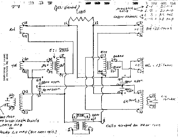
(See figure 4) If all conditions for the circuit are met with the proper component values and if the wiring is made according to the schematic diagram, the unit- should function and produce 300 to 500 watts of energy.
The only limiting factor to the amount of power that can be extracted is the wire size used in the coils and transformers. Hendershot on many occasions when applying excessive out-out loads, would burn up the unit by the over heating of the wiring. Some variations can be made in the circuit wiring but what changes can be made remain unknown at this time.
After a unit was wired either by Hendershot or other experimenters he would sit down at the device with a length of insulated wire bared at each end and begin making connections to various terminals of the unit until the solenoid-magnet combination would buzz and the output load, if it was a standard 110 volt light bulb, would glow. He then would adjust the air gap between the magnet and solenoid coils until full brilliance was achieved and the buzzer produced a steady tone. This procedure would take from a few minutes to several hours.
On one occasion he adjusted the unit for 10 to 15 minutes and only achieved a flash of light from the output. Several hours later he found it necessaray to rebuild the capacitors before any further tests could be made. Either the unit would work immediately or not at all, depending on the unknown characteristics of the phenomena.
MATERIAL LIST
2 Dual 40-80 MFD Electrolytic Capacitors 400 Volt Non-Polarized
2 5:1 Ratio 24 Volt to 120 Volt Transformers (Vertical OscillatorType)
Red, Black, Blue, Green Coded Wires
250' #20 AWG Insulated Solid Copper Wire
100' #28 Enamel Copper Wire
500' #24 Enamel Copper Wire
114 311 x 11811 Wood Dowels
1 Horseshoe or U Shaped Magnet
2 Plates for Dowel Pin Mounting
1 Screw Type Adjusting Mechanism
1 1-1/211 x 1180 x 611 Flat Iron Bar (Approx.)
2 Iron Solenoid Cores
Miscellaneous parts, screws, bolts, wire, etc.